The counter is basically the scintillator plastic wrapped up to prevent external light from entering it and attached to a photo multiplier tube (PMT). Particles passing through the scintillator create light which is then detected by the PMT.The scintillator has a round disk, called a cookie, glued to one corner which the PMT is placed against to detect the light that is created by the particles.
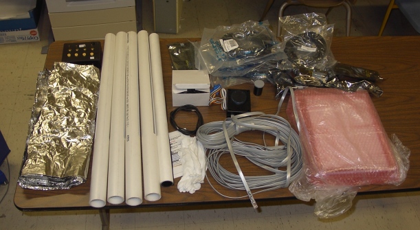
First thing in assembling a counter is having all the parts and tools ready. The cosmic ray detector came with most of what we need to assemble the counters: the plastic scintillator, with the cookie, heavy duty aluminum foil, black light blocking paper, the slotted PVC pipe, a photo multiplier tube, and optical grease. Everything that came with the cosmic ray detector can be see in the picture at the right (the scintillators are in the pink bubble wrap). The GPS, power distribution box, DAQ board, and all the cables and wires required to hook everything together are also shown. In addition to these things provided we needed 3/4" and 3" black electrical tape, 1/2" Teflon plumber's tape, and an applicator stick for the optical grease. Helpful tools included scissors, a razor blade, ruler, and protractor.
Before we started wrapping the scintillator up we cleaned it off by wiping it, including the cookie, with a lint free cloth dampened with isopropyl alcohol. The scintillator plastic was handled only using cloth gloves which were provided with the detector kit. The gloves prevent any oil or dirt from getting on the scintillator from our hands.
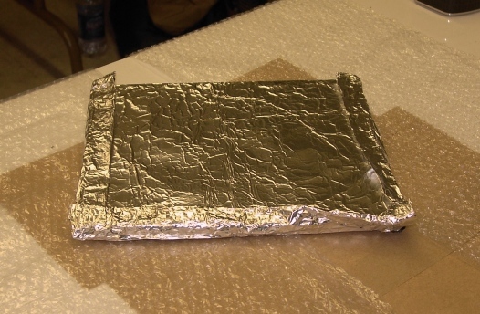
The first layer of wrapping was the aluminum foil. The foil's reflective surface helps to keep unwanted light out and light created by particles in, where it can be detected by the photo multiplier tube. The foil came in a large sheet that must be cut into four pieces, one for each counter. Each piece, once cut, measured about 19" by 32". One piece was then laid out, "shiny" side up, and the scintillator place on top. The foil was folded over and around the plastic, rather like wrapping a present up. The picture at the left is the wrapped scintillator. The foil was removed from the cookie by carefully cutting around the base of the cookie with a razor blade. The light is detected by the PMT through the cookie so it must be open. Any tears in the foil were patched using small pieces of foil and the 3/4" electrical tape. The bare edges of the cookie were covered with the Teflon plumber's tape, taking care not to cover the face of the cookie.
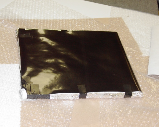
The next layer of covering was the black paper. The paper was black on one side, white on the other, thick, and lightproof. It also came in one large sheet like the foil and had to be cut into four pieces. These pieces were about 9" by 27" each. Since the paper is so thick it was not wrapped around the edges the way the foil was. Instead it just covered each face going around a short edge. It was taped securely in place with the 3/4" electrical tape. The covered scintillator is shown in the picture at the right. The exposed edges of the foil were then covered using the 3" electrical tape. The area around the cookie was carefully covered and the corners were reinforced with extra tape.
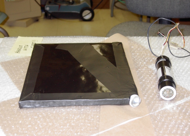
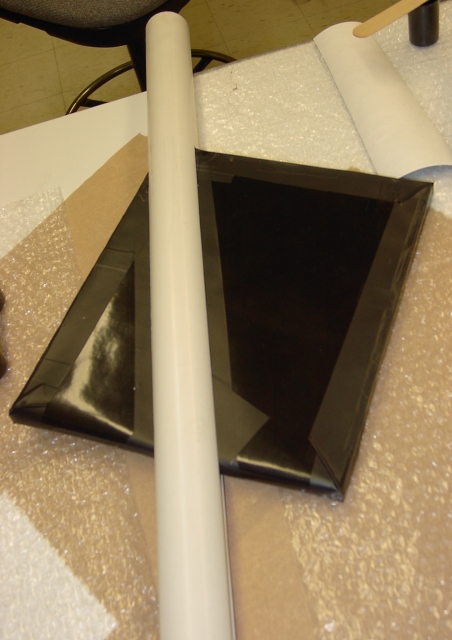
To protect the black paper from damage when the scintillator assembly is inserted into the PVC pipe a piece of 3" electrical tape was placed across it. The tape was run across the face of the scintillator starting at the cookie and continuing to the opposite edge at an 18° angle from long side of the scintillator. Both sides were taped. This picture (left) shows the scintillator taped and the photo multiplier tube sitting next to it.
With the scintillator covered the next step was to attach the photo multiplier tube. Using the applicator (a wooden tongue depressor) a pea sized portion of the optical grease was applied to the PMT face. Then the PMT and the cookie were held in contact and then gently pressed together. The PMT was moved around in a small circle to spread the grease to the whole surface of the cookie and PMT. Then the PMT was held firmly in place while it was taped to the scintillator using the 3" and the 3/4" electrical tape.
The purpose of the PVC pipe is to provide support to the photo multiplier tube. The PVC pipe helps ensure that the PMT and the cookie remain in contact and are not jostled. The scintillator-PMT assembly was carefully inserted into the slot in the PVC pipe, the PMT foremost. The assembly was slid all the way down until it was resting against the bottom of the slot with the PVC pipe extending beyond the opposite edge of the scintillator. The picture to the right shows the assembly fully inserted into the pipe. The angle between the long side of the scintillator and the PVC pipe was then measured and adjusted to 18°. This angle maintains the alignment between the PMT and cookie faces.
Once the assembly was inserted into the PVC pipe and properly aligned it was taped in place using the 3" electrical tape. Tape was wrapped around the outside of the PVC pipe that extended beyond the scintillator to provide pressure and clamp the assembly inside the PVC slot.
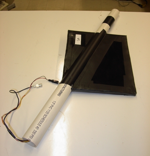
With the counter fully assembled it was connected and tested. Since counters one through four had already been assembled by this method this counter was labeled number five (left). Later counters six through eight were assembled using this method.